

I prepared for the pitot installation.
The pitot and aoa tubes need flares to connect them to the fittings.
Note that aviation flares are 37 degrees and that to automotive are 45 degrees and cannot be used!
- More info about flaring in these video’s:
The pitot tube is screwed to the mast with 4 #6-32 screws. Removing it for maintenance will be very difficult with all the fittings inside the wing. There is only 1 small oval shape inspection panel.
I came up with the idea to make the pitot with the mast removable and not rivet the mast to the 2 brackets.
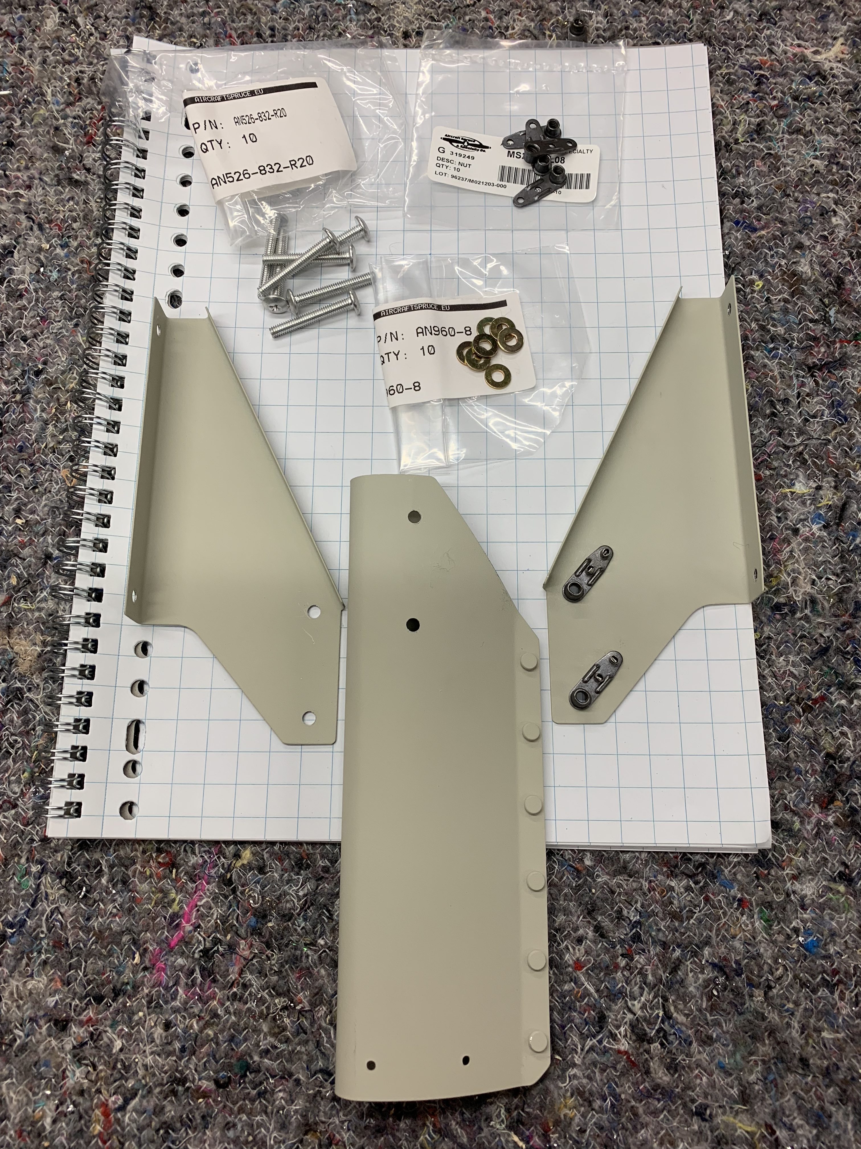
The holes in the mast are 3.2 mm, I up-sized them to 4.1 mm and mounted 2 #8-32 nutplates with 2.4 mm countersunk rivets:
In SolidWorks I designed a spacer:

- There are several options to make the spacer:
I tried letting the model print in black PA6 Nylon with FDM technology but without luck, the model did not stay straight during the printing.
So I changed to SLS 3d printing in white PA12 Nylon, this technology is using powder and a laser burns the model layer by layer.
The PA12 material is tested to 121 degrees Celcius, but is this enough for heat coming from the pitot?
The Garmin manual says that the minimum length of the tubes should be 8 inch to prevent heat damage to the plastic tubes, the spacer is within these 8 inch.
Luckily Peter V. did a test and found out that the maximum temperature near the spacer will be around 30 degrees Celcium – many thanks Peter!
So the PA12 material should be good to use.
- With the pitot and mast removable it should be easy to remove the pitot for maintenance:
I made a cardboard template of the mainspar and locations of the pitot and nylon tubes:

I’m not sure if I make 45 or 90 degrees bends, here the dimension of the radius for 90 degrees:

The pitot tubes should be screwed to the mast with patched screws #6-32 according the manual, these seem to be magical in Europe, I could not find a vendor. Many thanks to Doug W. for reselling and shipping a couple of these screws:

One more thing to investigate is about thread sealant for the pitot and aoa tubes, there is a rule that Teflon tape is a no-go for airplanes, although some use it but only for non-fluid fittings. I’ve asked Stein Air where I purchased this kit from. They say that it’s no problem to use Teflon tape, however I do need a sealant for the fuel tanks, so why not using it for the pitot as well. So I purchased some Loctite 577.
Now let’s wait until the 3d printed spacer is ready and then the real installation can start.